| **Buttons 1-4** | Buttons 1 to 4 are contextual to the current screen. **Short Click** : They allow you to switch tabs or pages on the current screen, or perform a specific action when a modal window is displayed. **Long Click** : Opens the parameter modulation assignment located above on the screen. |
| **360° Rotary Potentiometers 1-4** | Potentiometers 1 to 4 are contextual to the parameters displayed on the screen. There are up to 4 parameters presented simultaneously on the screen, each potentiometer controls the parameter located above it on the screen. |
| **Digital Encoder** | The encoder is contextual to the current screen. It allows you to navigate through menus, different instruments, or scroll through various wavetables or samples. **Short Click**: Confirms a selection on the screen. |
| **Exit / Alt Button** | **Short Click**: "EXIT" Button: Returns to the previous page. **Long Click: "ALT" Button**: Accesses alternative functionalities, generally allows access to additional tabs in the modules. **Long Click + Potentiometer 1-4**: Resets the parameter above the potentiometer to its default value. **Short click + encoder click:** preview the current instrument; the note lasts as long as the encoder is held. **Long click + turn encoder**: opens a shortcut menu. |
| **Audio Outputs 1-4** | Audio outputs 1-4 are AC-Coupled, with a voltage range of -7.5V to 7.5V. |
| **CV Inputs A-F** | CV inputs A-F operate within a voltage range of -5V to 5V. These inputs can be used for pitch control (standard 1V/oct) or modulation. Assignments are made in the software. |
| **Gate Inputs 1-4** | Gate inputs 1-4 operate within a voltage range of 0 to 40V. The trigger threshold is approximately 0.7V. |
| **Entrées CV G-L** | CV inputs G-L operate within a voltage range of -5V to 5V. These inputs can be used for pitch control (standard 1V/oct) or modulation. Assignments are made in the software. |
| **Entrées Gate 5-6** | Gate inputs 5-6 operate within a voltage range of 0 to 40V. The trigger threshold is approximately 0.7V. |
| **MIDI In** | Midi input is compatible with midi to jack 3.5 adapter (format TRS A or TRS B) |
| **Power** | Standard eurorack power -12V / GND / +12V , Red stripe of the ribbon is on the left |
| **MicroUSB** | Micro USB socket, to connect to a computer, used to update the firmware |
| **Extension** | Extension port, used to plug the CV/Gate & Midi extension
Warning ! The ribbon cable must be plugged in the right direction. There is a "RED" inscription on the PCB which indicates where the red stripe of the ribbon should be. |
Warning ! The ribbon cable must be plugged in the right direction. There is a "RED" inscription on the PCB which indicates where the red stripe of the ribbon should be.
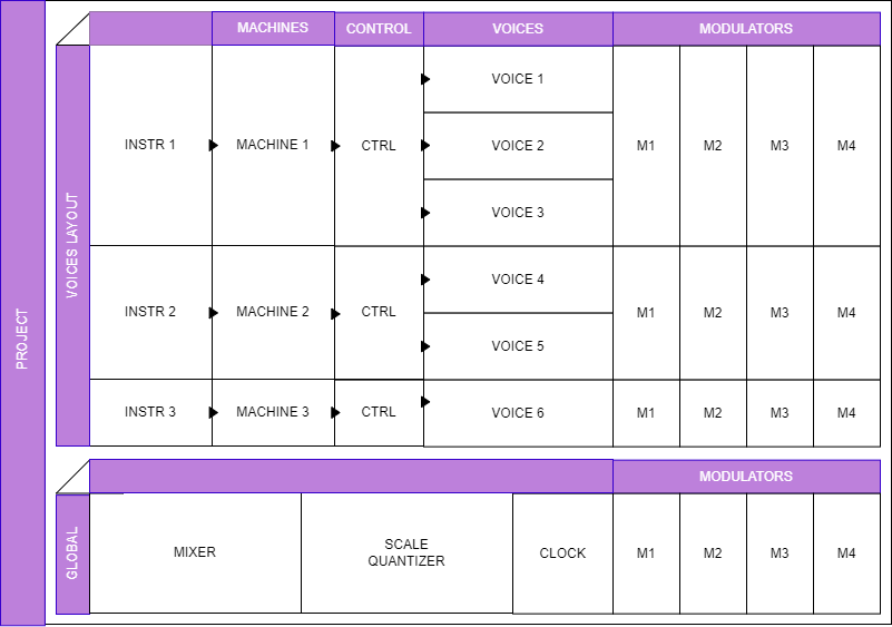
# Screen navigation (todo) # Understanding Antigone's architecture ## Introduction Antigone offers an architecture that may seem complex, but it is ultimately quite simple to understand if you take the time to explore it. ## The Projects The concept of a project is very similar to the projects offered by Elektron machines (such as the Digitakt, …). The project is the foundation of everything within Antigone. Projects can be compared to presets, patches, or programs found in some other modules or synthesizers. Here is the general schematic of a sample project that we will refer to multiple times in this section of the documentation. Keep an eye on it as you read.| **Components** | **Role** | **Learn More** |
| a machine | an algorithm capable of generating sound using a specific sound synthesis. At the time of writing this documentation, there are 4 different types of machines, each offering very different sounds, giving Antigone a wide range of sound palettes. | *coming soon* |
| a controller | whose parameters define how the instrument behaves when you control it | *coming soon* |
| 4 modulators | capable of running in parallel, these modulators will allow you to complicate the behavior of their instrument over time.
Although common to an instrument, you will be able to define specific modulation parameters for each of its voices. This makes Antigone very, very powerful. | *coming soon* |
| **Components** | **Role** | **Learn More** |
| a mixer | A mixing table defining the behavior of each instrument in the project at the audio level: volume, pan | *coming soon* |
| a scale quantizer | This component confines the notes played within a defined scale and transposed pitch. | *coming soon* |
| a clock | This module allows you to define the clock parameters used to synchronize the module's behaviors. This clock can be either internal or external to the module. | *coming soon* |
| 4 global modulators | Capable of running in parallel, these modulators will allow you to complicate the overall behavior of the project over time. | *coming soon* |
| A modulation matrix | This component allows you to visualize the entirety of a project's modulations within a matrix. | *coming soon* |
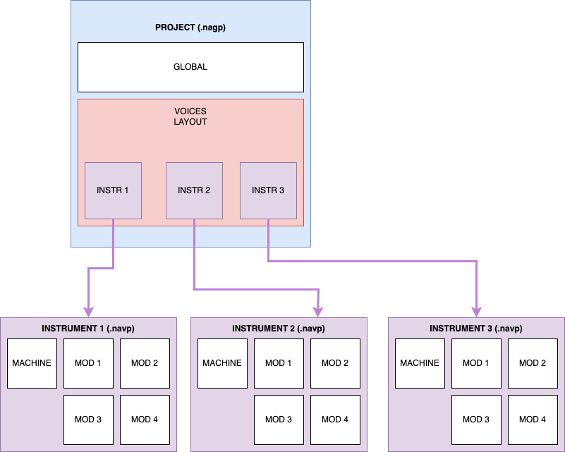
| **Concepts** | **File Content** | **File Type** |
| Project | All the components that define it (the global parameters, the voice layout used, and the configuration of each instrument). It is, therefore, complete and autonomous. | .nagp |
| Instrument | A machine and its modulations.
You can use this file type to save a reusable instrument in another project. | .navp |
Important concept: For each project, you will be able to define the control type. It is crucial to understand that the control type is not set globally for your module, but rather within each individual project. Therefore, changing the control type of one project will not affect other projects on the SD card.
From the project's home screen, select instrument number 1, then click on the encoder. [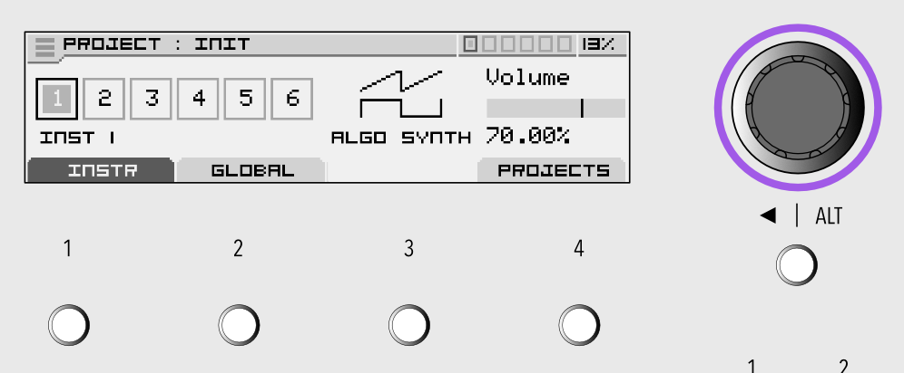](https://nanopolis.storage.googleapis.com/uploads/images/gallery/2025-04/eyJimage.png) Once you're in the instrument, turn the encoder all the way to the right to reach the last item, "CONTROL". [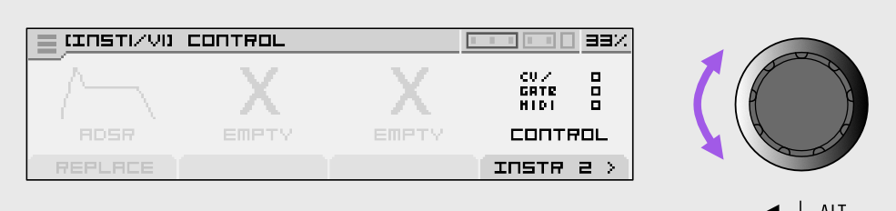](https://nanopolis.storage.googleapis.com/uploads/images/gallery/2025-04/0A3image.png) Once on "CONTROL", press the encoder. You'll arrive at the "Instrument Control" screen. 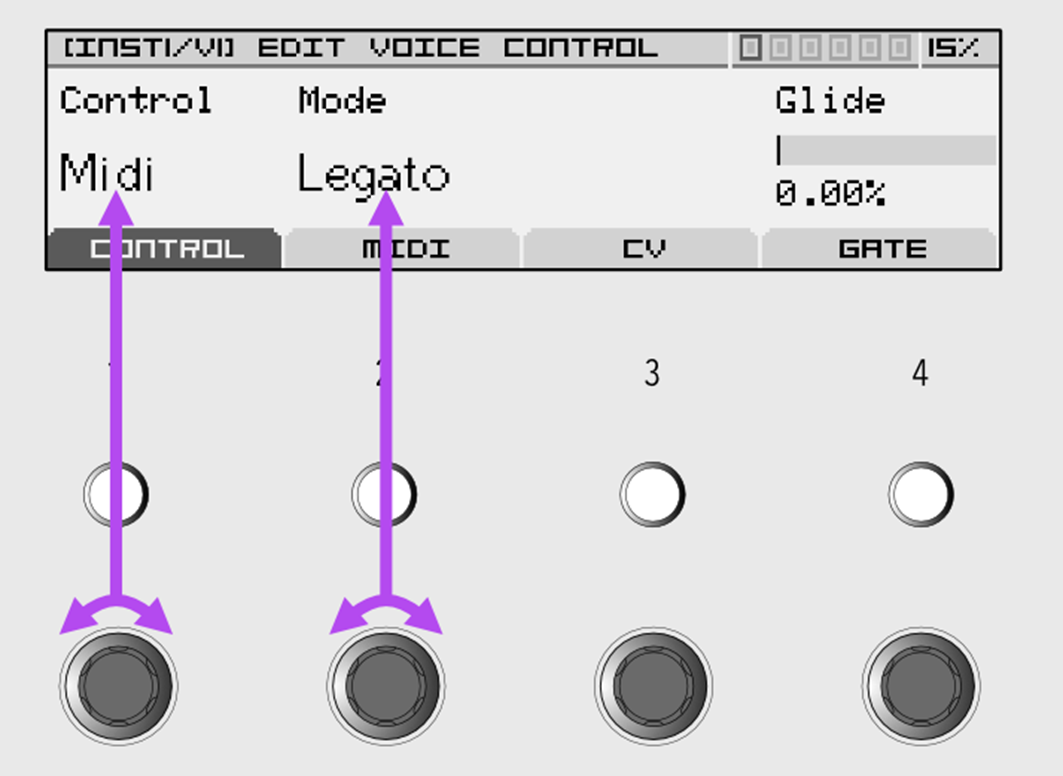 Select the type of control you want by turning the first potentiometer located directly below the "Control" parameter. You can also change the mode by turning the second potentiometer. ### CV/Gate In CV/Gate control mode, you can use a compatible keyboard or controller. [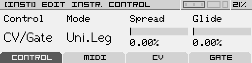](https://nanopolis.storage.googleapis.com/uploads/images/gallery/2025-03/5xRscreenshot-004.png) Connect a cable to the "Gate 1" input of the module, and the other end to the "Gate" output of your keyboard. Connect another cable to the "CV IN A" input of the module, and the other end to the "CV" (or Control Voltage, or Pitch, etc.) output of your keyboard. 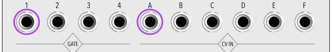 You should now be able to play and hear the sound being sent to outputs 1 and 2. ### Midi If you choose the MIDI protocol, you will need to have the MIDICVExpander.| [](https://nanopolis.storage.googleapis.com/uploads/images/gallery/2025-03/ZA2screenshot-002.png) You can connect a TRS Type A or B cable to the designated input on the expander and connect the other end to the MIDI OUT of your MIDI-compatible keyboard. 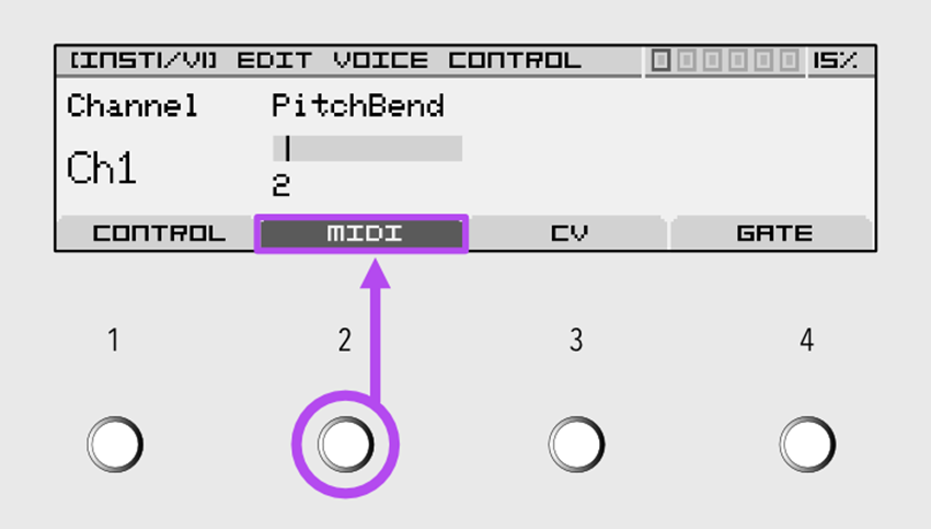From the MIDI tab, accessible by pressing button 2 on this screen, you will have the option to set the MIDI channel and the Pitch Bend range. | 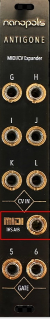 MIDICV Expander |
This voice configuration is what we call the "VOICE LAYOUT" in Antigone. A full section on configuring this layout is available in this documentation.
This voice representation is always visible in the screen header: [](https://nanopolis.storage.googleapis.com/uploads/images/gallery/2025-03/kgTimage.png) and always lets you know which instrument you're currently editing. The voices also light up when a note is played. ##### Instrument Name and Icon| [](https://nanopolis.storage.googleapis.com/uploads/images/gallery/2025-03/FiKimage.png) | Below the voice layout, you’ll see the name of the selected instrument. Here, it's labeled "INST 1" by default. If a preset exists, its name will be used instead. |
| [](https://nanopolis.storage.googleapis.com/uploads/images/gallery/2025-03/eV5image.png) | And to the right of the voice layout, there is the icon representing the machine loaded into the instrument. |
| Used Sys Memory | This is the memory occupied by the system. This memory space is managed automatically and cannot be modified. This allocation represents approximately 4 MB of memory. |
| Used Wave Memory | This memory is used for loading samples and wavetables. This allocation represents approximately 12 MB of memory. If memory usage approaches 100%, you may no longer be able to load additional samples or wavetables. (A warning message will be displayed when loading in this case.) |
| Firmware version | Indicates the firmware version currently installed on the Antigone. |
An instrument can also be used as a simple oscillator, without filters, effects, or modulators. This is one of Antigone's strengths: a highly flexible architecture, seamlessly integrable into a modular environment, covering a wide range of uses.
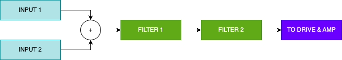
All parameters of an instrument (excluding the controller) can be saved on the SD card as a preset or template for later reuse. See the "[FILES AND TEMPLATES](https://doc.nanopol.is/books/en-antigone-documentation/page/file-templates-todo "Files & Templates (todo)")" section. #### Instrument Positioning Diagram in the Chain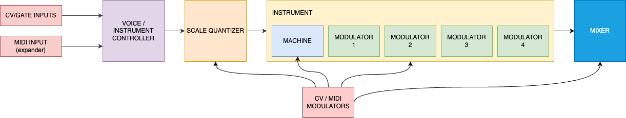
**Note:** Instrument control parameters are not saved within instrument presets. Since voice allocation is fixed to ensure usability and predictability in a modular environment, these settings are stored at the project level.
### Accessing the voice controller [ 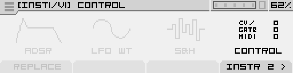](https://nanopolis.storage.googleapis.com/uploads/images/gallery/2025-03/screenshot-001.png) From the "PROJECT" main screen, select an instrument by clicking the encoder, then navigate to the "CONTROL" module on the far right. Click again to enter the "INSTR. CONTROL" screen. ### Configuration Page ##### [ 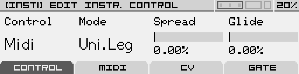](https://nanopolis.storage.googleapis.com/uploads/images/gallery/2025-03/HGGscreenshot-002.png)| **Name** | **Function** |
| **Control** | Defines how the instrument is controlled: - **Off**: Disabled - **CV/Gate**: Controlled via the CV/Gate inputs of Antigone and its expander - **MIDI**: Controlled via the MIDI input of the expander |
| **Mode** | The mode depends on the number of voices in the instrument. - **Mono**: Monophonic - **Legato**: Monophonic with legato (the envelope is not retriggered when changing notes) For instruments with multiple voices: - **Unison**: Plays the same note across all voices - **Unison Legato**: Unison mode with legato - **Poly**: Polyphonic mode |
| **Spread & Drift** (available for instruments with 2 or more voices) | **Spread**: In Unison mode, this parameter controls the amount of detuning between voices. **Drift**: In Poly mode, this simulates analog-style detuning between voices, adding warmth and character to the sound. |
| **Glide** | Enables a portamento effect (smooth pitch transition between notes). When set to 0.0%, this effect is completely disabled. |
**Reminder:** Antigone’s CV inputs are calibrated for the standard 1V/octave.
The following example shows a polyphonic instrument with 3 voices, controlled by CV inputs A, B, and C. CV inputs A-F belong to the main module, while inputs G-L belong to the expander. [ 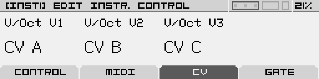](https://nanopolis.storage.googleapis.com/uploads/images/gallery/2025-03/screenshot-007.png) To configure which GATE inputs trigger envelopes (and other events) for each voice, go to the "GATE" tab and select the desired GATE inputs. GATE inputs 1-4 belong to the main module, while inputs 5 and 6 belong to the expander. [ 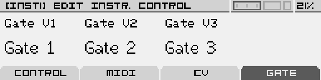](https://nanopolis.storage.googleapis.com/uploads/images/gallery/2025-03/screenshot-008.png) # Synthesis Machines There are 4 different Machines available in Antigone: Algorithmic Synth, Wavetable Synth, Sample Player and Crossmod. # Algorithmic Synth ## General information This Machine features 2 identical oscillators with 16 different algorithms to choose from. Each oscillator can be tuned, transposed and have its own algorithm (model).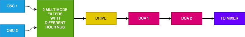
| **Model** | **Frequency** | **Transpose** | **Volume** |
| Select the synthesis type used in the oscillator | Fine-tune the oscillator. This can be used to achieve beating-effects by having th two oscillators slightly out of tune with each other | Tune the oscillator by one semitone increments. This can be used to have the Machine play a paraphonic interval, or use one oscillator as a sub | Adjust the volume at which the oscillator is sent down the signal path (to the Filter section, or directly the the Amp section if all filters are turned off). 100% is unity gain, but it can go up to 200% if you can to overdrive the Filters, Amps or even the final DAC. |
| **Sync** | **PhaseMod** | ||
| Above 0%, the saw wave is synced to a master oscillator. This adjusts the frequency of the slave oscillator you're hearing. Modulate for classic sync sounds | Above 0%, the saw wave's phase is modulated by another oscillator tuned at 0.75 times the frequency of the Saw. Increasing the parameter augments the modulation depth |
| **Density** | **Spread** | **Fade** | |
| Choose the number of saw waves in the swarm, up to 12 | Adjust the amount of detuning between the waves | Apply a volume fade on the most detuned saw waves to make the output less chaotic |
| **Simple<>Dual** | **PW** | **-** | **-** |
| Add harmonics by dividing the positive part of the pulse in three pulse segments | Adjust the pulse-width of the output wave. Modulate for classic PWM sounds | **-** | **-** |
| **Fold** | **Decimator** | ||
| Increase the number of folds in the wave to add harmonics. | Reduces the bit rate to add harmonics |
| **Fold** | **Sine<>Triangle** | **Transform** | **Decimator** |
| Increase the number of folds in the wave to add harmonics. | Crossfade between a sine and a triangle wave, which are out-of-phase with each other | Adjust the phase of the sine and skew the triangle | Reduces the bit rate to add harmonics |
| **OP4: Ratio** | **OP3: Ratio** | **OP2: Ratio** | **OP1: Ratio** |
| Adjust Operator 4 frequency, in multiples of the Carrier frequency | Adjust Operator 3 frequency, in multiples of the Carrier frequency | Adjust Operator 2 frequency, in multiples of the Carrier frequency | Adjust Operator 1 frequency, in multiples of the Carrier frequency |
Ratio parameters are stepped by 0.25 by default for more ease of use, but this can be free'd : Hold the button below the ratio parameter of the desired operator, then go to "SETTINGS" tab, then put "Stepped" parameter to off.
Page 3:| **OP4 : Depth** | **OP3 : Depth** | **OP2 : Depth** | **OP1 : Ph.Dis** |
| Amount at which Operator 4 modulates the target operator(s) | Amount at which Operator 3 modulates the target operator(s) | Amount at which Operator 2 modulates the target operator(s) | Amount of Phase distortion applied on the Sine. |
| **Mix B<>A** | **OP3 : Mode** | **OP2 : Mode** | **OP1 : Mode** |
| Mix between the outputs from 2 different operators, by default, it's 50% / 50% | It's how this operator is modulated, TZFM Linear 1, TZFM Linear 2, Linear or Exponential | It's how this operator is modulated, TZFM Linear 1, TZFM Linear 2, Linear or Exponential | It's how this operator is modulated, TZFM Linear 1, TZFM Linear 2, Linear or Exponential |
| **Ratio** | **Strength** | **Twist** | **Timbre** |
| Select the modulator frequency, being a multiple of the carrier frequency. | Non-linear gain of both the carrier and modulator signals | Distort the phase of the modulator oscillator | Morph from algorithm A to algorithm B |
| **Wave** | **DCW** | **Wave** | **DCW** |
| Select a target wave. If the second Wave parameter is not OFF, then this one will select a target wave for every odd cycle of the main sine. | Simulates a filter sweep by using a different phase modulation on each wave (combined with windowing on the Reso1, 2 and3 waves). At 0% only the main sine is heard, and at 100% only the target wave is heard. | Select a target wave for every even cycle of the main sine. | Simulates a filter sweep by using a different phase modulation on each wave (combined with windowing on the Reso1, 2 and3 waves). At 0% only the main sine is heard, and at 100% only the target wave is heard. |
| **S&H** | **Color** | ||
| The amout of time to hold the current sample. | To the left : cutoff from 0 to 100% Low pass filter. To the right : cutoff from 0 to 100% High pass filter |
Note that using 2048 samples wavetables are more CPU intensive than 256 sample wavetables. The sonic differences are negligible especially with the antialiasing enabled (Quality parameter)
680 free to use wavetables from WaveEdit Online [https://waveeditonline.com/](https://waveeditonline.com/) (released under the CC0 1.0 Universal Public Domain Dedication) are pre-loaded on the SD Card. You can also load custom wavetables using the SD card, you are only limited by the size of the SD Card. The oscillator will read 32/24/16 bits wavetables but play them in 16-bits. It will function with 2048, 1024, 512, 256 and 128 samples wavetables.User wavetables have to be put in folders, anywhere on the SD card. You can't mix different sample formats within a folder, and the folder name has to end with "\_XXX", with XXX being the sample format of the waves in the folder. For example "MyCustomWavetables\_1024" if the wavetables are in the 1024 samples-per-wave format.
The excellent wavetable editor from Synthesis Technology can be used to edit all these 256 samples wavetables: [https://synthtech.com/waveedit/](https://synthtech.com/waveedit/) The wavetable oscillator tab has 3 pages. Page 1:| **Position** | **Frequency** | **Transpose** | **Volume** |
| Navigate the wavetable. Modulate for classic wavetable morph sounds. | Fine-tune the oscillator. This can also be used to detune the oscillator from the sub oscillator for chorusing or dissonance effects | Tune the oscillator in semitone increments | Set the amplitude at which the oscillator is sent into the Filter Section. 100% is unity gain, beyond that the output is amplified, useful for driving the Filter or Amp sections or even overdriving the final DAC. |
| **Width** | **Phase** | **Transform** | **Depth** |
| Reduces the width of the waveform, without changing its pitch, by windowing it between blank spaces. It will affect the harmonics of the wave. | Change the starting point of the waveform. When using Width, it will scroll which segment of the wave is heard | Select one of the 6 wave-altering effects. See below for a reference of those. | Control the selected Transform effect |
| **Off** | **Sync** | **Sync Window** | **Asymmetry +/-** |
| The Transform effect is inactive | Simulates a sync effect. Depth will change the tuning of the master oscillator, the result is phase distortion. | Same as Sync but there is a "fade-in/fade-out" effect on the edges of the waveform in order to smooth out artifacts | Classic Phase Distortion. Depth is at 0% at noon, and turning it clockwise or counter-clockwise will distort the phase in either direction. |
| **Sine** | **Decimator** | **Folder** | **Triangle** |
| Phase distortion, but with a sine function instead of a linear function. | A bit-reducer effect. Turn Depth clockwise to reduce, down to 2bits, with an audio crossfading between the bit-rates. | A Chebyshev wavefolder | Triangle wave phase distortion |
| **Fractal** | **Bounce** | **Gravity** | **Tidal** |
| Fractal-like recursive phase folding | Multiple phase segments with alternating directions (1-8 bounces per cycle) | Phase acceleration toward center attraction point using inverse distance relationship | Slow multi-harmonic tidal waves with period variations |
| **Magnetic** | **Crystal** | **Steps** | **Quantum** |
| Dual magnetic poles with inverse square law force calculations | Geometric faceted patterns (3-8 crystal faces) with lattice spacing | Divides phase into discrete steps (2-16 levels) | Discrete energy levels (4-16) with probabilistic quantum jumps |
| **Fade** | **Collapse** | ||
| Applies fade windows of varying shapes based on transform depth | Wave collapse simulation with multiple attraction points |
| **Quality** | **Transition** | **-** | **-** |
| The amount of oversampling while reading the wavetable. Draft means no oversampling, resulting in aliasing on complex waves but low CPU usage. Above Draft, an anti-aliasing filter is present. Medium is x2 oversampling Great is x3 Highest is x4. It will use a lot of CPU power. | Select between classic wave interpolation or discrete change from one wave to another (no morph) | **-** | **-** |
| **Wave** | **Frequency** | **Transpose** | **Volume** |
| Select the sub oscillator's waveform between Saw, Square, Triangle, Sine and Wavetable. The Wavetable mode use the same wave as the main oscillator (without anti-aliasing, and without modfications) | Fine-tune the sub oscillator. | Tune the sub oscillator in semitone increments | Set the amplitude at which the sub oscillator is sent into the Filter Section |
| **Noise** | **-** | **-** | **-** |
| Set the amplitude at which the noise generator is sent into the Filter Section | - | - | - |
| **Frequency** | **Transpose** | **-** | **Volume** |
| Fine-tune the sample | Tune the sample in semitone increments | **-** | Set the amplitude at which the sample enters the Filter Section. 100% is unity gain; beyond that, the output is amplified, useful for quiet samples or driving the Filter and Amp sections (or even overdriving the final DAC). |
| **Start** | **Loop** | **Length** | **Playmode** |
| Set the starting point of the sample file | Set the loop point if one of the loop modes is activated | Set the sample's stopping point | Select the sample playback mode: - Forward - Forward Loop - Reverse - Reverse Loop This parameter cannot be modulated. |
| **Decimator** | **Sample Rate Reducer** | **Noise** | **-** |
| A bit-depth reduction effect. Turn Depth clockwise to reduce, down to 2 bits, with audio crossfading between bit rates. | An audio-rate sample-and-hold effect that introduces classic digital brightness and harmonics. Turn clockwise to lower the sample rate. | Mix white noise with the sample. The noise plays continuously, so adding an envelope to this parameter is recommended. | **-** |
| **Vol In 1** | **Vol In 2** | **Algo** | **Timbre** |
| Controls the volume of the Carrier voice | Controls the volume of the Modulator voice | Select one of the 6 cross-modulation algorithms. Refer to the chart below for an overview of those. This parameter cannot be modulated. | Depending on the choosen algorithm, it changes the timbre of the sound. (crossfade between dry and modulated sound for example) |
| **XOR** | **Modulo** | **Ring Modulation** | **Ring Modulation 2** | **Sub** | **Negative - Positive** |
| Performs cross-modulation between two audio signals using the bitwise XOR (exclusive OR) operation. | Performs cross-modulation between two audio signals using the modulo operation. | Performs a ring modulation between two audio signals. | Performs a diode based ring modulation between two audio signals. | Performs a gain then a substraction between two signals. | Keep the positive part of the first signal, and the negative part of the second signal. |
| **Filter 1 Frequency** | **Filter 1 Resonance** | ***(Filter Morph) -or- (Filter Gain)*** | **Filter 1 Type** |
| Controls the filter's cutoff frequency | Controls the filter's resonance amount | *Morph between the filter types, from Low-Pass to Notch to High-pass. This parameter is only available when the filter type is set to SVF for State Variable Filter.* *-or-* *Set the EQ gain. This parameter is only available when the filter type is set to Bell EQ.* | Select a filter type and slope. Read the filter types reference below for details on every filter available. This parameter cannot be modulated. |
| **Off** | The filter is bypassed |
| **SVF** | State Variable Filter model. Use Knob 3 to morph between filter types |
| **K35 LP12 / HP6** | Korg 35. Inspired by the MS-20 filter. |
| **TLD LP 6/12/18/24** | Transistor Ladder Filter model. Inspired by the classic Moog filter. Low-Pass with a selection of slopes from 6dB/oct to 24/dB/oct |
| **TLD N 12/24** | Transistor Ladder Filter model. Inspired by the classic Moog filter. Notch filter with 12dB/oct and 24dB/oct slopes |
| **TLD BP 12/24** | Transistor Ladder Filter model. Inspired by the classic Moog filter. Band-pass with 12dB/oct and 24dB/oct slopes |
| **DLD LP24** | Diode Ladder Filter model. Inspired by the TB-303 filter. Low-pass with a steep 24dB/oct slope. |
| **COMB +/-** | Comb filter for hollowed-out sounds and wooshes effects. With positive or negative feedback (resonance) |
| **FORMANT** | Formant filter for vowel sounds. Morph through A-E-I-O-U with Knob 1. |
| **BELL EQ** | Simple 1-band equalizer to increase or decrease a selected frequency region. Knob 2 will adjust the bell width and Knob 3 will set the gain |
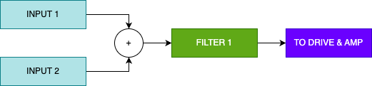
| **Routing** | **Balance between filter 1 and 2** | **-** | **-** |
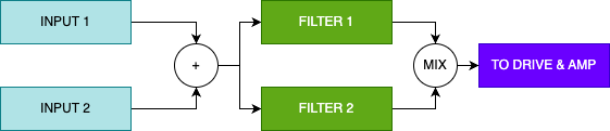
| Select a routing configuration for the filters. Single enables only filter 1. Serial routes the output of Filter 1 to Filter 2. Para will route both filters in parallel Split will split the sound sources into the two filters, depending on the Machine select. | Controls the volume of both filters at the output. Fully clockwise only filter 2 will be heard, and fully counter-clockwise it will be only filter 1. | - | - |
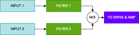
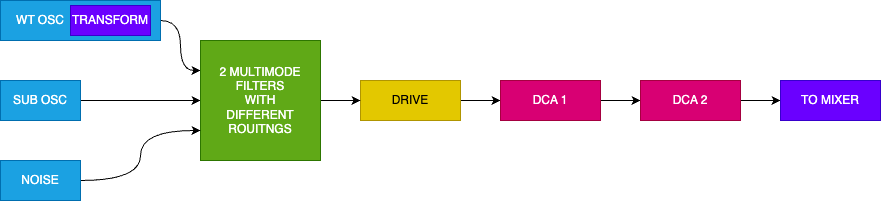
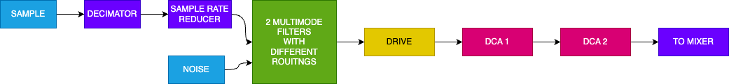
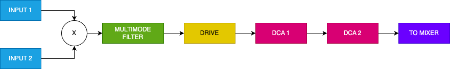
| Machine | Input 1 | Input 2 |
| Algo synth | Oscillator 1 | Oscillator 2 |
| Wavetable synth | WT Oscillator + Noise | Sub oscillator |
| Sample player | Sample | Noise |
| Crossmod | Crossmodulated output | - |
| **Drive Type** | **Drive** | ***DCA1*** | **DCA2** |
| Select one of the 29 distortion algorithms. Read the chart below for details regarding each one. | Controls the amount of distortion | The first Digitally Controlled Amplifier. DCA1 and DCA2 are routed in series, with 1 usually modulated by velocity and 2 modulated by an envelope. But you can set modulations as you wish. | The second Digitally Controlled Amplifier. DCA1 and DCA2 are routed in series, with 1 usually modulated by velocity and 2 modulated by an envelope. But you can set modulations as you wish. |
| **Type** | **Description** |
| **Off** | Bypassed |
| **Soft** | Applies a soft saturation effect to an audio sample by adjusting the input sample's amplitude based on a calculated drive factor, using a hyperbolic tangent function for non-linear distortion |
| **Medium** | Applies a medium saturation effect to an audio sample by scaling the input sample's amplitude with a drive factor and using an arctangent function to achieve a smoother, non-linear distortion. |
| **Hard** | Applies a hard saturation effect to an audio sample by manipulating the sample's amplitude with a drive factor and employing a combination of hyperbolic tangent and arctangent functions for a more aggressive, non-linear distortion. |
| **Diode** | Applies a diode-based non-linear distortion to an audio sample. It scales the input sample by a drive factor, processes it through a diode model for non-linear distortion, and then blends the processed signal with the original signal based on the drive amount, including a volume compensation factor. |
| **Demon** | Applies a distortion effect to an audio sample by scaling the sample with a drive factor, processing it through a sine function, and then applying a diode-like non-linearity, blending the result with the original sample based on the drive amount |
| **Soft Fold** | Applies a soft folding distortion to an audio sample by scaling the sample with a drive factor, processing it through a sine function to create a folding effect, and blending the result with the original sample based on the drive amount |
| **Diode Fold** | Applies a diode-based folding distortion to an audio sample by scaling the sample with a drive factor, processing it through a diode model and a sine function to create a folding effect, and blending the result with the original sample based on the drive amount, including volume compensation |
| **Dual Frequency** | Applies a frequency-dependent distortion to an audio sample by splitting the sample into low and high frequency components using simple filters, applying different saturation levels to each band, and then blending the processed bands with the original sample based on the drive amount |
| **Tube** | Simulates tube-like distortion by scaling the input sample with a drive factor, applying a non-linear transformation to mimic the tube saturation effect, and blending the processed signal with the original sample based on the drive amount |
| **Sigmoid** | Applies a tube-like distortion using a sigmoid function to achieve smooth non-linear saturation, scaling the input sample with a drive factor and blending the processed signal with the original sample based on the drive amount. |
| **Tape Dynamics** | Applies dynamic saturation by using a high-pass pre-emphasis filter, followed by a hyperbolic tangent saturation, and then a low-pass de-emphasis filter, blending the processed signal with the original sample based on the drive amount. |
| **Tape Hysteresis** | Models tape hysteresis by simulating magnetic hysteresis behavior, adjusting the input sample based on coercivity and remanence factors, and applying a hyperbolic tangent function to saturate the magnetization, blending the processed signal with the original sample based on the drive amount. |
| **Tape Curve** | Applies a tape saturation effect by approximating a saturation curve, scaling the input sample with a drive factor, and using a non-linear transformation to mimic the characteristic response of tape saturation |
| **Tape Noise** | Simulates tape saturation with added noise by generating white noise, applying a hyperbolic tangent saturation to the noisy signal, and blending the processed signal with the original sample based on the drive amount, including volume compensation for higher drive levels. |
| **Hard Clipping** | Applies a hard clipping distortion to an audio sample by limiting the sample's amplitude to a threshold determined by the drive factor, normalizing the output, and blending the processed signal with the original sample based on the drive amount |
| **Fuzz** | Applies a fuzz distortion effect to an audio sample by scaling the sample with a drive factor, using an exponential function to create a non-linear distortion, and blending the processed signal with the original sample based on the drive amount |
| **Chebyshev** | Applies a series of Chebyshev polynomials to an audio sample, using a normalized drive factor to create a complex harmonic distortion effect, and then blends the processed signal with the original sample based on the drive amount |
| **Half Rectifier** | Applies a half-wave rectification effect to an audio sample by zeroing out negative values, scaling the rectified signal with a drive factor, and blending the processed signal with the original sample based on the drive amount |
| **Full Rectifier** | Applies a full-wave rectification effect to an audio sample by taking the absolute value of the input sample, scaling it with a drive factor, and blending the processed signal with the original sample based on the drive amount |
| **Transistor** | Simulates transistor-like saturation by scaling the input sample with a drive factor, applying a non-linear transformation to mimic transistor saturation characteristics, and blending the processed signal with the original sample based on the drive amount. |
| **Dynamic** | Applies a dynamic distortion effect to an audio sample by scaling the sample with a drive factor that is modulated by the sample's envelope, using a hyperbolic tangent function for non-linear distortion, and blending the processed signal with the original sample based on the drive amount. |
| **Asymmetric** | Applies an asymmetric clipping distortion to an audio sample by limiting the sample's amplitude to different positive and negative thresholds based on a scaled drive factor, normalizing the clipped signal, and blending it with the original sample based on the drive amount. |
| **Feedback** | Applies a feedback-based distortion effect to an audio sample by adding a feedback signal, scaled by a gain factor derived from the drive, to the input sample and then applying a hyperbolic tangent function for non-linear distortion, updating the feedback with the processed sample |
| **Zero Crossing** | Introduces distortion at zero crossings by adding a small spike to the audio sample whenever it crosses zero, with the spike's magnitude determined by a normalized drive factor, and updates the last sample for future comparisons. |
| **Bit Reaper** | Applies a bit reduction effect to an audio sample by scaling the drive factor, using it to determine a decimation factor, and then applying a bitwise reduction to the sample, followed by a non-linear saturation using a hyperbolic tangent function, blending the processed signal with the original sample based on the drive amount |
| **Sample Reaper** | Applies a sample rate reduction effect by holding the last sample value for a duration determined by the drive factor, updating the sample only when a counter exceeds a threshold, and blending the processed signal with the original sample based on the drive amount |
| **Sample Reduction** | Reduces the sample rate of an audio signal by holding the current sample value for a number of iterations determined by a drive-scaled reduction factor, effectively lowering the perceived sample rate |
| **Bitwise** | Applies a bitwise distortion effect to an audio sample by performing an XOR operation between the sample and a drive-scaled value, then normalizing the result and scaling it based on the drive amount |
| **Ring Modulation** | Applies a ring modulation effect to an audio sample by multiplying the sample with a sine wave at a frequency determined by the drive factor, updating the phase of the modulating signal to maintain continuous modulation |
| Attack | Decay | Sustain | Release |
|---|---|---|---|
| Sets the time for the envelope to reach its peak level after the gate is activated (or a key is pressed in MIDI). | Sets the time for the envelope to drop to the Sustain level after Attack completes, while the gate remains high (or the key stays pressed in MIDI). | Defines the level at which the envelope remains as long as the gate is high (or the key is held in MIDI). | Sets the time for the envelope to return to its lowest level after the gate is released (or a key is released in MIDI). If the gate is released before Decay (or Attack) finishes, the envelope directly starts the Release stage from its current level, skipping Sustain (or both Decay and Sustain). |
| Curve A | Curve B | - | Curve C |
|---|---|---|---|
| Sets the Attack stage curve, from Logarithmic to Linear to Exponential. | Sets the Decay stage curve, from Exponential to Linear to Logarithmic. | - | Sets the Decay stage curve, from Exponential to Linear to Logarithmic. |
| Predelay | Hold | - | - |
|---|---|---|---|
| Sets the delay time before the Attack stage starts ramping up after the gate is activated (or a key is pressed in MIDI). | Sets the time the envelope is held at its peak after Attack completes and before Decay starts. | - | - |
| Trigger | Mode | Range | Retrig |
|---|---|---|---|
| Defines the source that triggers the envelope: - Disabled - Any of the 6 Gate inputs - Voice trigger (note on) - Clock signals | Defines how the envelope responds to gate signals: - **Gate**: Standard operation mode. - **Trigger**: The Sustain stage is skipped, and the envelope goes into Release after Decay. - **Loop**: The envelope cycles like a free-running LFO. - **Gated Loop**: The loop resets to the beginning of the Attack phase each time the gate goes high. | Selects the time range for the envelope: - Slow - Medium - Fast - Snap (optimized for percussive sounds) | Restarts the envelope from the beginning if retriggered before completion. |
| Gain | - | - | - |
|---|---|---|---|
| Adjusts the amplitude of the envelope signal, typically used for Velocity modulation. -100% means no output. | - | - | - |
| Wave | Phase | Speed / Clock / Ratio | - |
|---|---|---|---|
| Select an LFO wave by navigating the wavetable. | Adjust the phase offset, shifting the starting point of the waveform. | Set the LFO frequency. This parameter adapts based on the synchronization mode: - Free mode: frequency in Hz - Clock mode: divisions or multiplications of the MIDI Clock - Ratio mode: multiples of the Voice's oscillator frequency | - |
| Mode | Trigger | - | - |
|---|---|---|---|
| Choose the LFO synchronization mode: - **Free**: The LFO runs independently. - **Clock**: The LFO syncs to the incoming MIDI Clock signal. - **Ratio**: The LFO syncs to the Voice's oscillator frequency, tracking its pitch (useful for FM, AM, and other audio-rate modulations). | Defines the source that resets the LFO phase. Options include: - Any Gate input - Voice trigger signal - MIDI Clock divisions/multiplications Only available in Free mode. | - | - |
| Polarity | Gain | - | - |
|---|---|---|---|
| Select LFO polarity: - Bipolar - Unipolar positive - Unipolar negative | Adjust the LFO output level (can be modulated). | - | - |
| **Shape** | **Minimum** | **Maximum** | **Repeat** |
| Select one of the 34 shapes available | Stretch the shape by "squashing it" towards the top when you turn clockwise. Like resizing a picture. | Stretch the shape by "squashing it" towards the bottom when you turn counter-clockwise. Like resizing a picture. | A ratcheting effect. Set how many times the shape cycles, for the duration of the step. Select between 1 and 8 repeats |
| **Chance** | **Fade** | **-** | **-** |
| Set the probability for the step to play. If a step does not play, the sequencer output stays at the previous value until the step is completed. | Apply a fade-in (counter-clockwise) or a fade-out (clockwise) to the shape | - | - |
| **Steps** | **Play Mode** | **-** | **-** |
| Select the number of steps in the sequence, from 1 to 256. Can be modulated. | Select how the sequence is played. The options are: Off (freezes on the currently playing step, looping it), Forward, Reverse, Ping-Pong and Random. Can be modulated. | - | - |
| **Trig Mode** | **Clock** | **Trigger** | **-** |
| Select how the sequencer moves to the next step. Clock means it advances at the selected clock rate, Trigger means it advances each time the specified trigger is received. | Select the rate at which the steps and their shapes are played back, in divisions or multiplications of the Clock. If the sequencer is in Clock mode, this will also be the rate at which the sequencer moves to the next step. | Select a source to advance the sequencer in Trigger Mode. It can be any of the Gate Inputs, or the same signal that triggers the Voice. | - |
| **Polarity** | **Gain** | **-** | **-** |
| Select the sequence output polarity between : - bipolar - unipolar positive - unipolar negative. Can be modulated. | Set the level of the sequence output. Can be modulated | - | - |
| Source | Trigger | - | - |
|---|---|---|---|
| The signal to be sampled can be internal noise, any CV input, modulators from any voice or global sources, Macros, or even any Voice output. Additionally, it includes a selection of MIDI parameters such as Velocity, Key Follow, Aftertouch, and ModWheel. | The S&H can be triggered by any of the Gate inputs, the Voice trigger, or various divisions and multiplications of the MIDI clock. A small dot indicator will activate each time a trigger is received, signaling that a new sample has been taken. | - | - |
| Polarity | Gain | - | - |
|---|---|---|---|
| Select the polarity of the S&H signal: - Bipolar - Unipolar Positive - Unipolar Negative | Adjust the level of the S&H signal. This parameter can be modulated. | - | - |
| **SOURCE** | **Description** |
| VOICE M1 to M4 <NAME> | Modulator loaded in slots 1 to 4 of the instrument <NAME> is the name of the modulator (ADSR, LFOWT, ...) |
| VELOCITY (MIDI only) | Note velocity |
| KEYFOLLOW | Keyboard tracking based on the played note |
| MIDI AT (MIDI only) | MIDI Aftertouch control |
| MIDI MW (MIDI only) | MIDI Mod Wheel control |
| GLOBAL M1 to M4 <NAME> | Modulator loaded in global modulator slots 1 to 4 <NAME> is the name of the modulator (ADSR, LFOWT, ...) |
| EXTERNAL CV A to L | Uses module inputs (A–F) or expander inputs (G–L) as modulation sources |
| INTERNAL NOISE | Uses internal white noise generator as modulation source |
| MACRO 1...16 | Project macros 1 to 16 |
| VOICE 1...6 OUTPUT | Uses the voice audio output as modulation source |
| V1 to V6 M1...M4 <NAME> | Modulator loaded in slots 1 to 4 of a specific voice (1 to 6) <NAME> is the modulator name (ADSR, LFOWT, ...) Allows cross-voice modulation |
Note that you cannot create new modulations from within the matrix. Modulations can significantly impact CPU usage. Avoid keeping unnecessary modulations active—such as those with an attenuverter set to 0%, or modulations relying on a missing source (EMPTY).
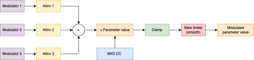
# Global modulation ### Operation Antigone provides 4 global modulation slots at the project level. These modulations can be used in the same way as instrument-level modulations, with the key difference that they cannot be triggered by notes played on the instruments. The global modulation management interface is similar to that of instrument modulations. It presents four empty slots that the user can fill with different types of modulators, including: - LFO Wavetable - ADSR (Attack-Decay-Sustain-Release Envelope) - S&H (Sample & Hold) - Shape Sequencer #### Global Modulation Management Screen [ ](https://nanopolis.storage.googleapis.com/uploads/images/gallery/2025-03/g6Hscreenshot-003.png) ### Advantages of Global Modulation Global modulations are optimized for efficient CPU usage. Unlike modulations applied individually to each voice of an instrument, they consume fewer resources, making them an ideal solution for continuous modulators such as LFOs or shape sequencers. To optimize performance and reduce CPU load, it is recommended to use global modulations whenever possible. This allows for rich and dynamic modulations without overloading the available resources for individual instruments. ### Accessing Global Modulation [ 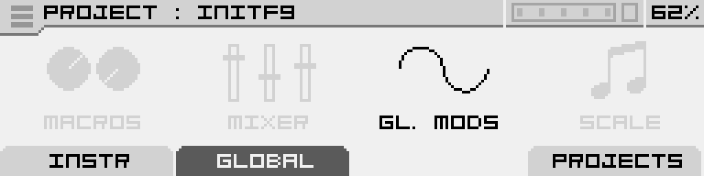](https://nanopolis.storage.googleapis.com/uploads/images/gallery/2025-03/gl-mods.png) You can access global modulations from the main "PROJECT" screen by navigating to the "GLOBAL" tab. Select "GL. MODS," then click the encoder to enter the "GLOBAL MODULATORS" screen. ### Slot Management #### Adding a Modulator [ ](https://nanopolis.storage.googleapis.com/uploads/images/gallery/2025-03/AtAscreenshot-001.png) To add a modulator, select an empty slot by turning the encoder left or right, then click the encoder or press the "ADD" button. This will open a list of available modulators that you can assign to the selected slot. [ 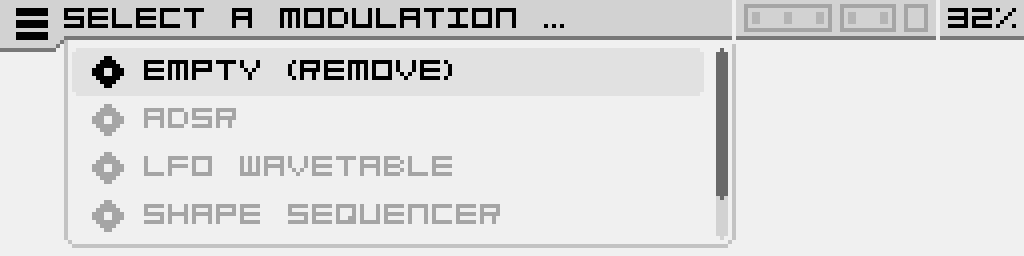](https://nanopolis.storage.googleapis.com/uploads/images/gallery/2025-03/0uDscreenshot-004.png) Confirm your selection by clicking the encoder. #### Replacing a Modulator If a slot already contains a modulator, you can replace it by selecting the "Replace" option. This allows you to quickly change the type of modulator assigned to the slot. [ ](https://nanopolis.storage.googleapis.com/uploads/images/gallery/2025-03/A4vscreenshot-002.png) #### Navigating Between Slots The encoder allows you to navigate between different slots. Clicking on an occupied slot provides direct access to the modulator’s parameters. # General features # Macros ### Operation In Antigone, you can define up to 16 macros per project. These macros allow you to simultaneously control one or more parameters, with varying degrees of influence depending on the parameter. Macros are part of the modulation system: they are considered modulators within Antigone. You can assign a macro to a parameter in the same way as any other internal or external modulator.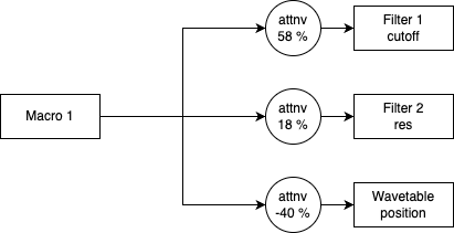
| **Volume** | The instrument's volume, adjustable from 0 to 100%. |
| **Pan** | The instrument's position in the stereo field (left-right). This parameter is only active when a stereo output is selected. |
| **Spread** | The distribution of the instrument’s voices across the stereo spectrum. This parameter is only active when a stereo output is selected and allows you to adjust the stereo image of the instrument. |
| **Output** | **Off**: The instrument's audio output is disabled. **OUT 1 to 4**: The instrument outputs in mono on one of Antigone’s audio outputs 1 to 4. **OUT 1-2 or 3-4**: The instrument outputs in stereo on Antigone’s audio outputs 1-2 or 3-4. |
| **Transpose** | Allows transposition (in semitones) of all Antigone voices. This transposition occurs before the Scale Quantizer. |
| **Scale** | Allows selection of a musical scale. When "Off" is selected, no quantization is applied. (See the next chapter) |
| **RootNote** | Defines the fundamental note. |
| **Scale parameter value** | **Scale name** | **Intervals** |
| Chrom. | Chromatic | 0, 1, 2, 3, 4, 5, 6, 7, 8, 9, 10, 11 |
| Pent.Min. | Minor Pentatonic | 0, 3, 5, 7, 10 |
| Pent. Maj. | Major Pentatonic | 0, 2, 4, 7, 9 |
| Harm.Min. | Harmonic Minor | 0, 2, 3, 5, 7, 8, 11 |
| Melo.Min. | Melodic Minor | 0, 2, 3, 5, 7, 9, 11 |
| Blues | Blues | 0, 3, 5, 6, 7, 10 |
| Lydian | Lydian | 0, 2, 4, 6, 7, 9, 10 |
| Aeolian | Aeolian | 0, 2, 3, 5, 7, 8, 10 |
| Sup.Loc. | Super Locrian | 0, 1, 3, 4, 6, 8, 10 |
| Locrian | Locrian | 0, 1, 3, 5, 6, 8, 10 |
| Dorian | Dorian | 0, 2, 3, 5, 7, 9, 10 |
| Augmen. | Augmented | 0, 3, 4, 7, 8, 11 |
| Mixoly. | Mixolydian | 0, 2, 4, 5, 7, 9, 10 |
| Phrygian | Phrygian | 0, 1, 3, 5, 7, 8, 10 |
| Gypsy | Gypsy | 0, 2, 3, 6, 7, 8, 10 |
| Persian | Persian | 0, 1, 4, 5, 6, 8, 11 |
| **Voice 1-6** | Allows individual transposition (in semitones) of Antigone's voices. This transposition occurs before the Scale Quantizer. |
| Gate 1..4 | Uses Gate 1 to 4 inputs as the clock synchronization source (1/16 division) |
| Gate 5..6 | Uses Gate 5 or 6 input from the expander as the clock synchronization source (1/16 division) |
| MIDI CLK | Uses the MIDI input from the expander as the clock synchronization source (96 ppqn) |
| Gate 1..4 | Uses Gate 1 to 4 inputs as the reset source |
| Gate 5..6 | Uses Gate 5 or 6 input from the expander as the reset source |
| MIDI STA | Uses the MIDI Start command received on the expander's MIDI input |
| MIDI STO | Uses the MIDI Stop command received on the expander's MIDI input |
Warning: The contents of the SD card have changed since version 1.0.0, please perform step 6 of this manual if you had a version lower than 1.0.0, otherwise the module will not start.
Click on the icon [](https://nanopolis.storage.googleapis.com/uploads/images/gallery/2024-05/6XRimage.png) and choose the firmware .hex file (example: antigone-1.0.0-beta.hex), then click on the "Auto" button so it lights up green as shown in the screenshot above. ### Step 6: Press the Button [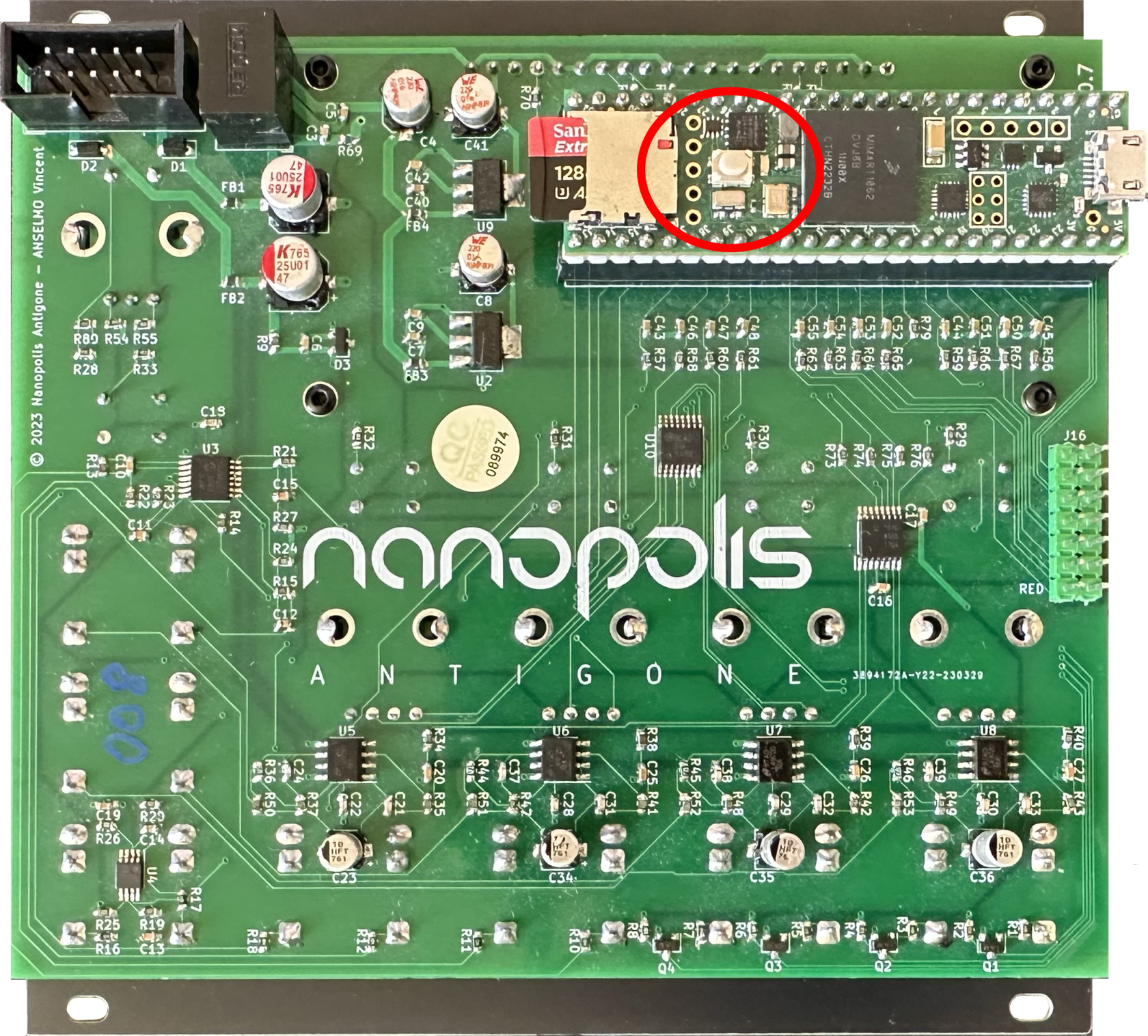](https://nanopolis.storage.googleapis.com/uploads/images/gallery/2024-05/I6Dimage.png) Press the button circled in red in the photo above. The firmware will update automatically. Once the message "Reboot OK" appears, you can remove the USB cable and put the Antigone module back into your Eurorack case. [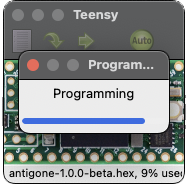 ](https://nanopolis.storage.googleapis.com/uploads/images/gallery/2024-05/JtEimage.png)[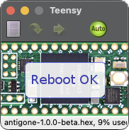](https://nanopolis.storage.googleapis.com/uploads/images/gallery/2024-05/wrIimage.png) You can check if the new version is properly installed by redoing step 1 ### Step 7: Reinitialize the Micro SD Card The micro SD card of the module must be formatted to exFat. (Factory formatting is already in exFat format) Download the factory microSD card content here: [https://storage.googleapis.com/nanopolis/firmwares/SDCard-v1.1.4.zip](https://storage.googleapis.com/nanopolis/firmwares/SDCard-v1.1.4.zip) Unzip the downloaded zip file, and copy all directories to your microSD card (Instruments, Projects, Samples, System and Wavetables) The contents of the card should look like this, the Instruments, Projects, Samples, System and Wavetables directories should be at the root of the SD card.| On Mac it must look like | On WIndows it must look like |
| [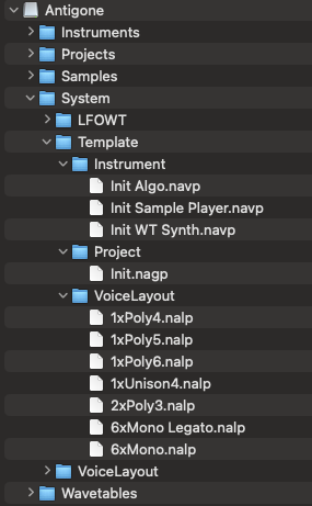](https://nanopolis.storage.googleapis.com/uploads/images/gallery/2024-06/wvZimage.png) | [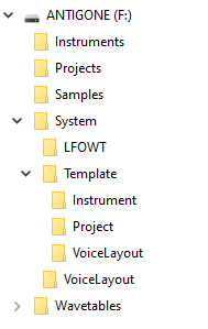](https://nanopolis.storage.googleapis.com/uploads/images/gallery/2024-08/image.png) |
Warning: As soon as Test Mode is activated, a 440 Hz sine wave signal will be emitted simultaneously on all four audio outputs (1/2/3/4). This helps detect potential audio output malfunctions.
### Details of the different tests #### PSRAM [ 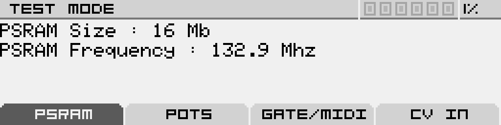](https://nanopolis.storage.googleapis.com/uploads/images/gallery/2025-03/screenshot-002.png) • Checks the amount of detected memory. • The expected values are "PSRAM Size: 16MB" and "PSRAM Frequency: 132.9MHz". • If less than 16MB is detected, this indicates an issue with one of the PSRAM components. #### POTS (Potentiometers) [ 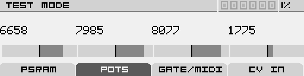](https://nanopolis.storage.googleapis.com/uploads/images/gallery/2025-03/screenshot-003.png) • Allows you to test the functionality of the endless rotary potentiometers. • As you rotate each of the four endless potentiometers, you should see the bar gradually move left or right. #### GATE/MIDI [ 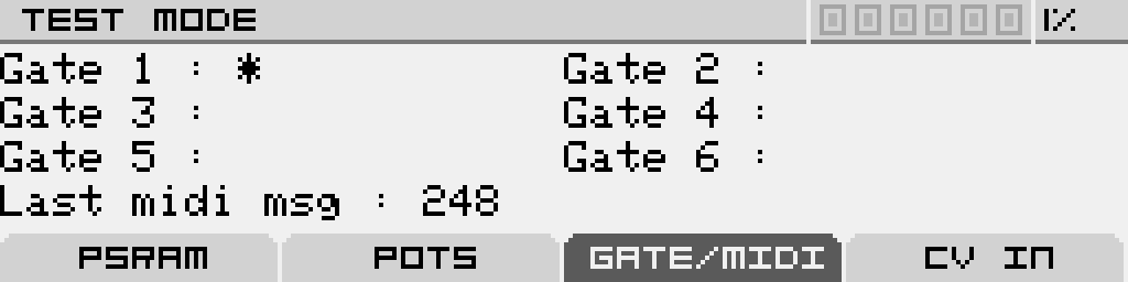](https://nanopolis.storage.googleapis.com/uploads/images/gallery/2025-03/screenshot-004.png) • Verifies the GATE inputs of the main module (1-4) and the expander (5-6). • A ‘\*’ symbol appears next to the input name when a voltage is detected. • "Last MIDI Message" displays the last received MIDI message (if the MIDI expander is connected). • If no MIDI message is displayed, this indicates an issue with the MIDI input. #### CV [ 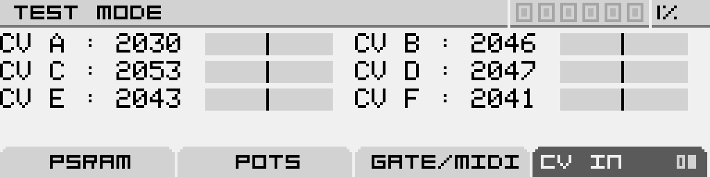](https://nanopolis.storage.googleapis.com/uploads/images/gallery/2025-03/screenshot-005.png) • Displays the real-time value of the CV inputs, ranging from 0 to 4095: • 0 = -5V • 2047 ≈ 0V • 4095 = +5V The displayed values are raw readings received from the ADC (Analog to Digital Converter) without calibration or smoothing. It is normal to see some fluctuations in the values and for the center value at 0V to not be exactly 2047. It may vary by +/- 20 values. This deviation is corrected during the calibration process. # Calibration Antigone’s calibration ensures accurate CV input response according to the 1V/oct standard. If an expander is connected, it is recommended to restart the full calibration process to properly include and adjust the new CV inputs. Calibration data is stored in Antigone’s Flash memory and remains intact after a firmware update. Therefore, recalibration is not required after updating the firmware. ### How to start the calibration? On Antigone’s main screen "PROJECT", click the burger menu using the encoder, then go to the "SETTINGS" menu and click again to enter. [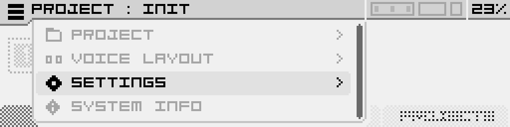](https://nanopolis.storage.googleapis.com/uploads/images/gallery/2025-03/vAescreenshot-001.png) Then select "CALIBRATION". [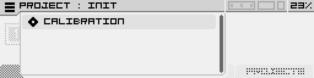](https://nanopolis.storage.googleapis.com/uploads/images/gallery/2025-03/aL6screenshot-002.png) In the calibration screen, you will be asked to unplug all cables connected to the CV inputs (on both the module and the expander). Next, connect a keyboard (or any voltage source) to the CV A input as shown, and press the C3 key on your keyboard, which usually outputs 0 Volts (depending on your master keyboard’s settings). [ ](https://nanopolis.storage.googleapis.com/uploads/images/gallery/2025-03/xgMscreenshot-003.png) Then click the "NEXT" button (button 4) to begin calibration of CV input A. Wait until the progress bar completes. [](https://nanopolis.storage.googleapis.com/uploads/images/gallery/2025-03/DQ6screenshot-004.png) Unplug the cable from CV input A, plug it into CV input B, and repeat the process for each CV input: \- A to F for the main module \- then G to L if the expander is connected. Once the 0 Volt calibration is done, repeat the entire process for all inputs again using a 3V signal, which corresponds to the C6 note.After completing the full calibration process, it is recommended to restart the module.