Modulators
ADSR
The ADSR is an essential modulator for synthesis. In this case, it is a DAHDSR (Delay-Attack-Hold-Decay-Sustain-Release) envelope.
The main features of this ADSR are:
- 6-stage envelope (Delay-Attack-Hold-Decay-Sustain-Release)
- Configurable curve for Attack, Delay, and Release stages
- Multiple modes (Gate, Trig, Loop, and Gated Loop)
- The envelope can restart when retriggered before finishing (or continue)
- Like other modulators, the output gain can be modulated to function as a "Depth" parameter.
Keep in mind that every envelope parameter can be modulated, except those in the Settings tab, which define the envelope's behavior.
All values are displayed in %. Time values depend on the Range settings (Snap, Fast, Medium, Slow).
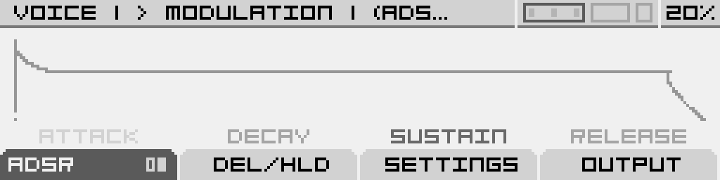
Main ADSR Screen
ADSR Tab
The ADSR tab consists of two pages, navigable by pressing the corresponding button (button 1).
Page 1 allows you to modify (and modulate) envelope times:
| Attack | Decay | Sustain | Release |
|---|---|---|---|
| Sets the time for the envelope to reach its peak level after the gate is activated (or a key is pressed in MIDI). | Sets the time for the envelope to drop to the Sustain level after Attack completes, while the gate remains high (or the key stays pressed in MIDI). | Defines the level at which the envelope remains as long as the gate is high (or the key is held in MIDI). | Sets the time for the envelope to return to its lowest level after the gate is released (or a key is released in MIDI). If the gate is released before Decay (or Attack) finishes, the envelope directly starts the Release stage from its current level, skipping Sustain (or both Decay and Sustain). |
Page 2 allows you to modify (and modulate) envelope curves:
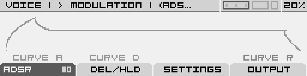
| Curve A | Curve B | - | Curve C |
|---|---|---|---|
| Sets the Attack stage curve, from Logarithmic to Linear to Exponential. | Sets the Decay stage curve, from Exponential to Linear to Logarithmic. | - | Sets the Decay stage curve, from Exponential to Linear to Logarithmic. |
Delay/Hold Tab
This tab allows you to add segments to the ADSR envelope:
| Predelay | Hold | - | - |
|---|---|---|---|
| Sets the delay time before the Attack stage starts ramping up after the gate is activated (or a key is pressed in MIDI). | Sets the time the envelope is held at its peak after Attack completes and before Decay starts. | - | - |
Settings Tab
This tab contains settings that define the envelope behavior. These settings cannot be modulated.
| Trigger | Mode | Range | Retrig |
|---|---|---|---|
Defines the source that triggers the envelope:
|
Defines how the envelope responds to gate signals:
|
Selects the time range for the envelope:
|
Restarts the envelope from the beginning if retriggered before completion. |
Output Tab
A final gain stage for the envelope, which can be modulated:
| Gain | - | - | - |
|---|---|---|---|
| Adjusts the amplitude of the envelope signal, typically used for Velocity modulation. -100% means no output. |
- | - | - |
LFO Wavetable
This is a Low-Frequency Oscillator (LFO) that provides a wide range of waveforms through wavetables.
Main features of this LFO:
- Any wavetable can be used, allowing you to browse and select individual waves as modulation sources.
- In Free mode, multiple frequency ranges are available:
- Slow: 0.0003 Hz to 2.22 kHz
- Medium: 0.01 Hz to 81.9 Hz
- Fast: 0.5 Hz to 4095 Hz - Synchronization options allow the LFO to sync to an external clock signal.
- Syncing to the Voice's main oscillator frequency is possible, enabling FM-like modulation (0.25× to 24× the oscillator frequency).
- The LFO can be retriggered at the start by a trigger source (note, clock, or gate input).
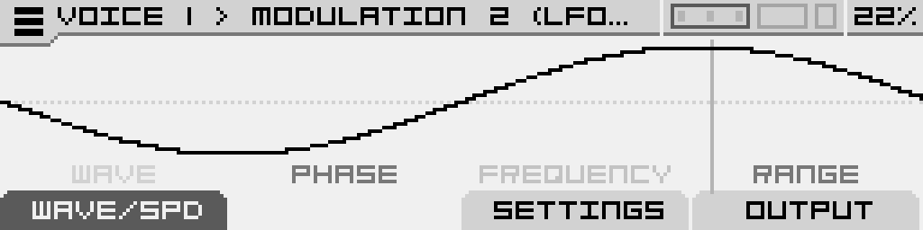
Main screen of the Wavetable LFO
On any page of the Wavetable LFO, turn the Encoder to browse through wavetables. Click the Encoder to access the Browser and manually load a wavetable.
In the Browser:
- Press Button 1 to navigate up a folder level.
- Press Button 4 to enable Autoload, allowing real-time auditioning.
- Click the Encoder to open a selected folder or load a chosen wavetable file.
Wave/Speed Tab
This section allows you to configure basic LFO parameters:
| Wave | Phase | Speed / Clock / Ratio | - |
|---|---|---|---|
| Select an LFO wave by navigating the wavetable. | Adjust the phase offset, shifting the starting point of the waveform. | Set the LFO frequency. This parameter adapts based on the synchronization mode:
|
- |
Settings Tab
This section defines the LFO's run mode and retrigger behavior. These settings cannot be modulated.
| Mode | Trigger | - | - |
|---|---|---|---|
Choose the LFO synchronization mode:
|
Defines the source that resets the LFO phase. Options include:
Only available in Free mode. |
- | - |
Output Tab
Modify the LFO signal before sending it to modulation targets:
| Polarity | Gain | - | - |
|---|---|---|---|
Select LFO polarity:
|
Adjust the LFO output level (can be modulated). | - | - |
Shape sequencer
This is an advanced modulator that lets you draw complex automation envelopes, create wave-sequencing effects, or even simple sequences, on a per-step basis.
Main features of this shape sequencer :
- Sequence from 1 to 256 steps
- Can be played in forward, reverse, ping-pong or random
- Steps can be synchronized to a clock (1/64, 1/32, 1/16, 1/4, 1/2, 1 BAR, 2BAR, 4BAR, 8BAR, 16BAR)...
- ...or be trigged manually using a gate input, or a Note On (if used as an instrument modulator)
- Multiple parameters per step (Shape, min value, max value, repeat (from 1 to 8), chance, fade in/out
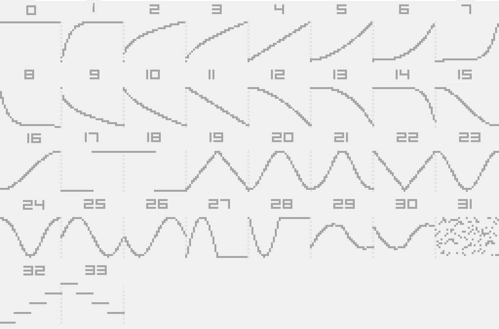
- 34 different shapes available
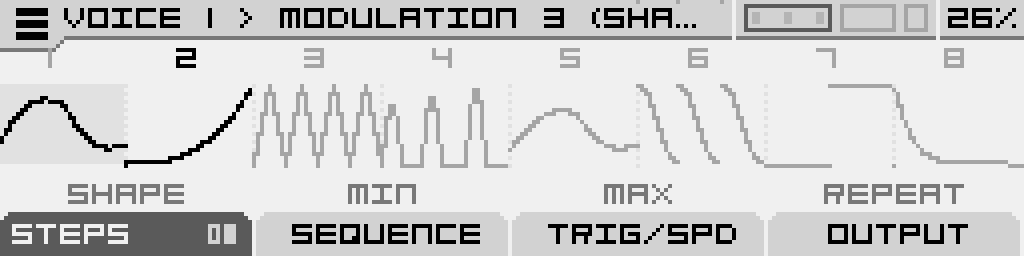
Main screen of the shape sequencer (in edit mode)
The shape sequencer comes in two different working modes :
- Edit mode : more suitable to precisely edit all parameter for a selected step. The 4 potentiometers in this case controls different parameters of this step
- Perf mode : more suitable in "live", to edit the same parameter on different step using the four potentiometers (corresponding to 4 different steps)
Menu
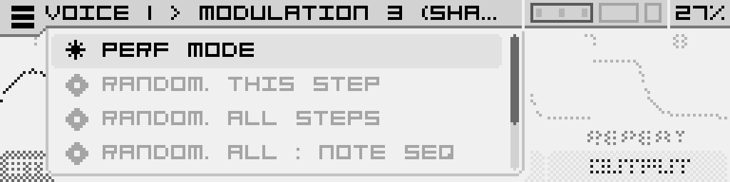
Click the Encoder to bring up a contextual menu which contains the following operations:
- Perf Mode : switch to Performance Mode (Please refer to the paragraph below for more informations on this)
- Randomize This Step - selects a random shape for the currently selected step
- Randomize All Steps - selects a random shape for each and every step of the sequencer
- Randomize All : Note Seq - generates a random sequence of fixed values, like a standard step-sequencer
- Randomize All : Pluck Seq - generates a sequence of plucked shapes with ratcheting
- Reset all - initializes the entire sequence to the default template
Click the encoder to launch the selected operation.
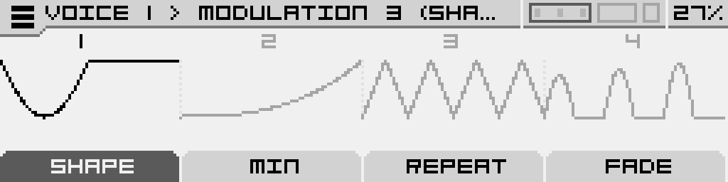
Steps Tab
Edit Mode
This is the default mode of operating the sequencer, and the one you land on when first opening the Shape Sequencer.
Turn the Encoder to scroll to the step you want to edit, which is the one highlighted, one page contains 8 steps, it automatically change the page after 8 steps.
The Steps tab has 2 pages. Click its button (Button 1) to cycle between pages.
Page 1 allows you to select and modify the shape of the selected step. Note that these parameters cannot be modulated.
| Shape | Minimum | Maximum | Repeat |
| Select one of the 34 shapes available | Stretch the shape by "squashing it" towards the top when you turn clockwise. Like resizing a picture. | Stretch the shape by "squashing it" towards the bottom when you turn counter-clockwise. Like resizing a picture. |
A ratcheting effect. Set how many times the shape cycles, for the duration of the step. Select between 1 and 8 repeats |
Page 2 contains more parameters for the selected step. Note that these parameters cannot be modulated.
| Chance | Fade | - | - |
| Set the probability for the step to play. If a step does not play, the sequencer output stays at the previous value until the step is completed. | Apply a fade-in (counter-clockwise) or a fade-out (clockwise) to the shape | - | - |
Performance Mode
It's an alternative display mode for the Shape Sequencer where all the parameter of the Steps tab from Edit Mode are remapped so you can edit the same parameter across multiple steps quickly. Note that these parameters cannot be modulated.
4 steps are displayed at a time, and you can drag the display across the sequence by scrolling the encoder.
Click one of the buttons to select the parameter you want to edit, which is labelled on the corresponding tab.
Tab 2 and Tab 4 have two pages each, respectively Min/Max and Chance/Fade.
Knob 1 will edit the selected parameter for step 1, Knob 2 will edit the selected parameter for step 2, and so on.
It's always the same sequence that you're editing, so you can freely toggle between Edit and Performance Mode.
Click the Encoder to bring up the same contextual menu as in Edit Mode, but in this one the first option is to switch back to Edit Mode.
You will need to be in Edit Mode to access the other tabs of the Shape Sequencer :
Sequence Tab
Here you will find the main parameter of the sequencer:
| Steps | Play Mode | - | - |
| Select the number of steps in the sequence, from 1 to 256. Can be modulated. |
Select how the sequence is played. The options are: Off (freezes on the currently playing step, looping it), Forward, Reverse, Ping-Pong and Random. Can be modulated. |
- | - |
Trigger / Speed Tab
Here you will find parameters regarding the sequence playback. Note that these parameters cannot be modulated.
| Trig Mode | Clock | Trigger | - |
| Select how the sequencer moves to the next step. Clock means it advances at the selected clock rate, Trigger means it advances each time the specified trigger is received. |
Select the rate at which the steps and their shapes are played back, in divisions or multiplications of the Clock. If the sequencer is in Clock mode, this will also be the rate at which the sequencer moves to the next step. |
Select a source to advance the sequencer in Trigger Mode. It can be any of the Gate Inputs, or the same signal that triggers the Voice. | - |
Output Tab
Here you can sculpt the sequence output before it's sent to the modulation targets:
| Polarity | Gain | - | - |
|
Select the sequence output polarity between :
Can be modulated. |
Set the level of the sequence output.
Can be modulated |
- | - |
Shapes reference
Sample & Hold
A Sample & Hold virtual circuit that reads an input in real time (external or internal) and takes a "snapshot" of this input whenever it receives a trigger signal. This snapshot is a fixed value that will be output until a new "snapshot" is taken.
On any page of the S&H modulator, a visual display provides a rough outline of the source signal and the sampled value.
Main screen of the Sample & Hold modulator
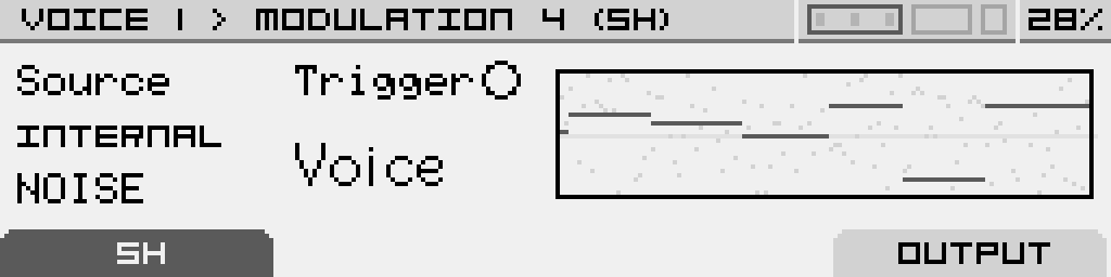
On the real-time chart displayed on the screen, the input source is shown in a faded background, while the sampled output appears in black.
The trigger parameter has a small indicator that lights up whenever a trigger signal is received.
S&H Tab
This section allows you to configure the basic parameters for the Sample & Hold:
| Source | Trigger | - | - |
|---|---|---|---|
| The signal to be sampled can be internal noise, any CV input, modulators from any voice or global sources, Macros, or even any Voice output. Additionally, it includes a selection of MIDI parameters such as Velocity, Key Follow, Aftertouch, and ModWheel. | The S&H can be triggered by any of the Gate inputs, the Voice trigger, or various divisions and multiplications of the MIDI clock. A small dot indicator will activate each time a trigger is received, signaling that a new sample has been taken. |
- | - |
Output Tab
This section allows you to shape the S&H signal before it is sent to modulation targets:
| Polarity | Gain | - | - |
|---|---|---|---|
|
Select the polarity of the S&H signal:
|
Adjust the level of the S&H signal. This parameter can be modulated. | - | - |