Annex
How to update the firmware ?
Step 1: Checking the current firmware installed
The current firmware version installed on your module is displayed at the module startup.
You can also check the version installed by moving the encoder to the left until you reach the burger menu, click on the encoder, and move until the "SYSTEM INFO" menu.
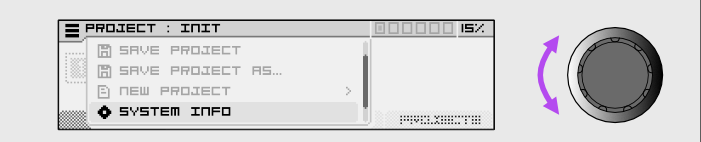
Click on the encoder again, you'll reach this screen :
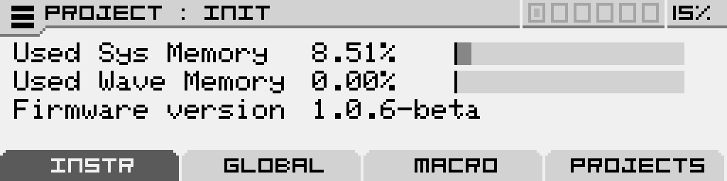
On which you can see the memory used by the system, the memory used by the wavetables and the version of the firmware installed.
Step 2 : Download the Firmware Update Tool (teensyloader)
The tool for loading new firmware is available for Windows, Macintosh, and Linux operating systems.
Download link for Windows version:
https://www.pjrc.com/teensy/teensy.exe
Download link for Macintosh (Apple) version:
https://www.pjrc.com/teensy/teensy.dmg
Explanation link for Linux (Ubuntu) installation:
https://www.pjrc.com/teensy/loader_linux.html
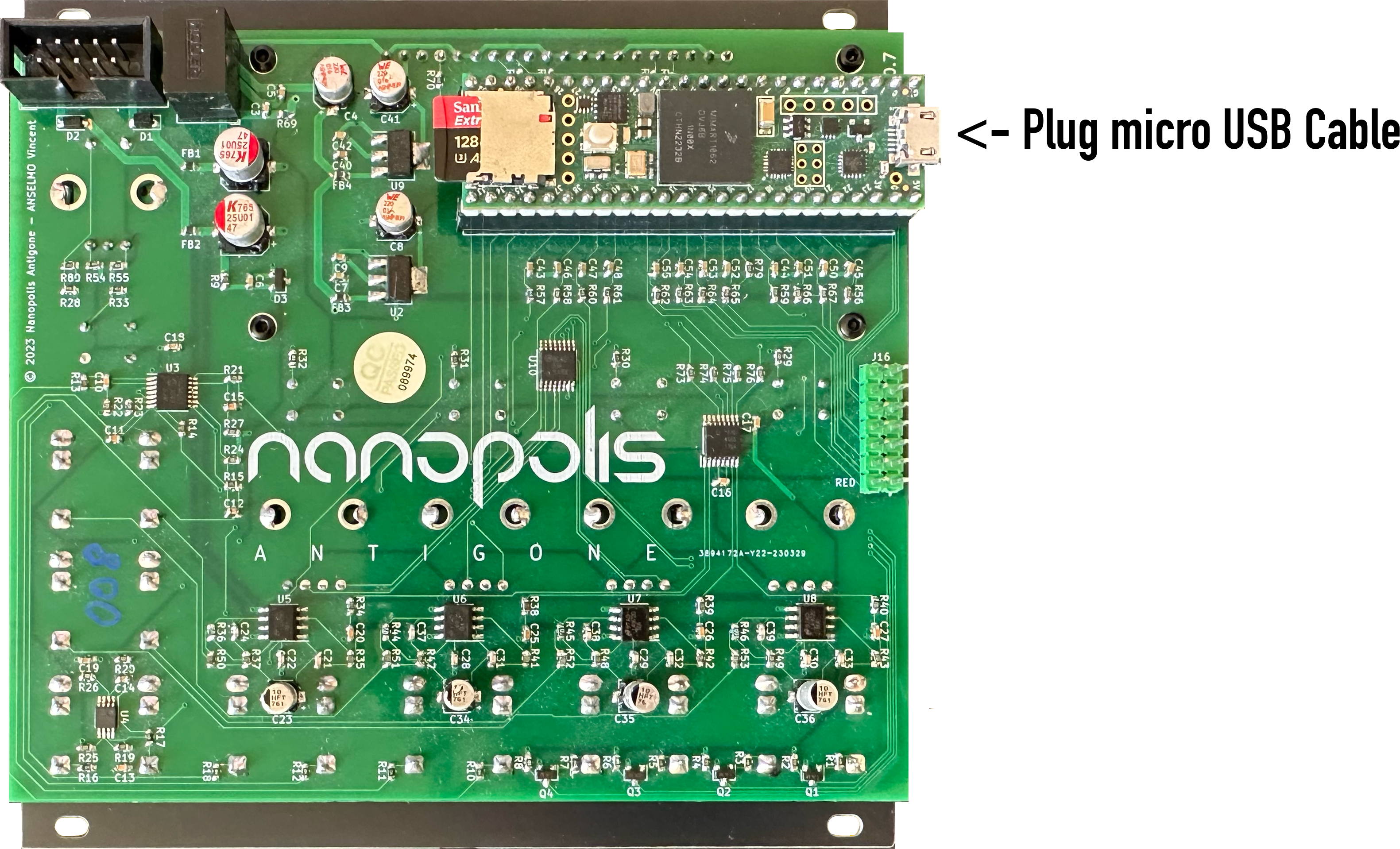
Step 3 : Connect the Antigone Module
Connect the Antigone using a standard micro USB cable to your computer.
Step 4 : Run Teensy Loader
Executez l'outil de chargement du firmware précédemment téléchargé
Step 5: Open the .hex Firmware File
Download the latest firmware version here :
https://storage.googleapis.com/nanopolis/firmwares/antigone-1.1.5.hex
Warning: The contents of the SD card have changed since version 1.0.0, please perform step 6 of this manual if you had a version lower than 1.0.0, otherwise the module will not start.
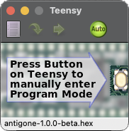
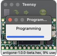
Click on the icon  and choose the firmware .hex file (example: antigone-1.0.0-beta.hex), then click on the "Auto" button so it lights up green as shown in the screenshot above.
Step 6: Press the Button
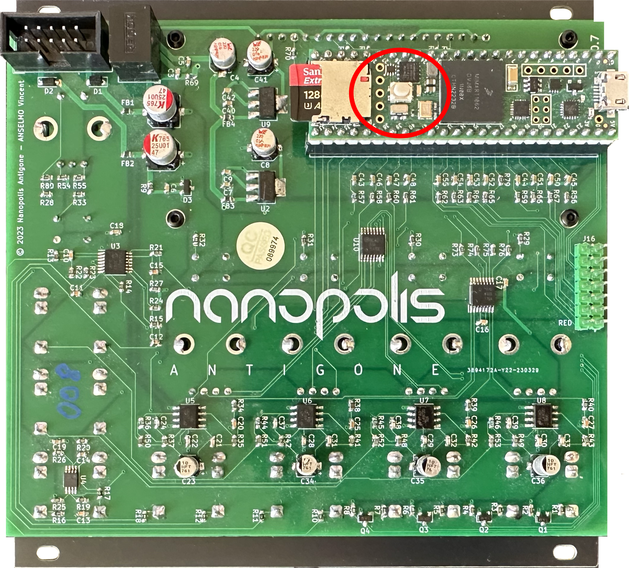
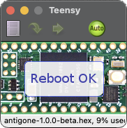
Press the button circled in red in the photo above. The firmware will update automatically. Once the message "Reboot OK" appears, you can remove the USB cable and put the Antigone module back into your Eurorack case.
You can check if the new version is properly installed by redoing step 1
Step 7: Reinitialize the Micro SD Card
The micro SD card of the module must be formatted to exFat. (Factory formatting is already in exFat format)
Download the factory microSD card content here:
https://storage.googleapis.com/nanopolis/firmwares/SDCard-v1.1.4.zip
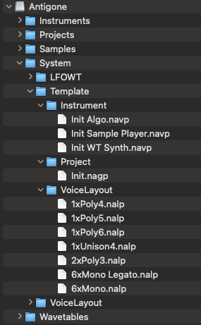
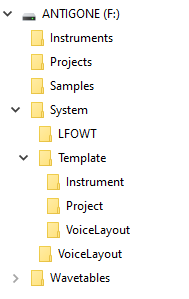
Unzip the downloaded zip file, and copy all directories to your microSD card (Instruments, Projects, Samples, System and Wavetables)
The contents of the card should look like this, the Instruments, Projects, Samples, System and Wavetables directories should be at the root of the SD card.
| On Mac it must look like | On WIndows it must look like |
 |
 |
Test mode
Functionality
The Test Mode allows you to verify the proper functioning of the hardware components of your main module and its expander. It includes tests for:
- Memory components (PSRAM)
- Audio outputs
- GATE inputs
- Endless rotary potentiometers
- CV inputs
How to activate Test Mode?
To activate Test Mode, hold the "< | ALT" button while powering on the module.
Warning: As soon as Test Mode is activated, a 440 Hz sine wave signal will be emitted simultaneously on all four audio outputs (1/2/3/4). This helps detect potential audio output malfunctions.
Details of the different tests
PSRAM
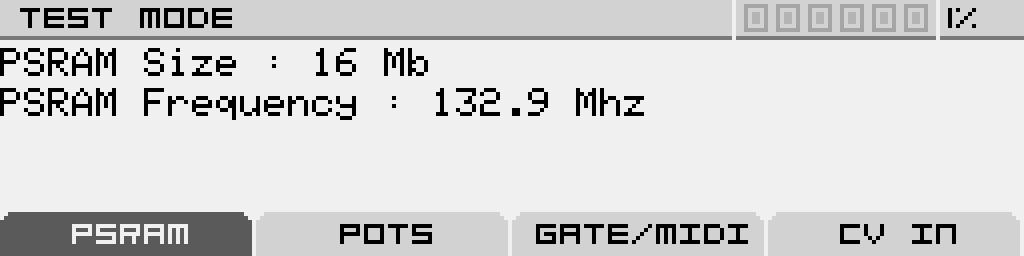
• Checks the amount of detected memory.
• The expected values are "PSRAM Size: 16MB" and "PSRAM Frequency: 132.9MHz".
• If less than 16MB is detected, this indicates an issue with one of the PSRAM components.
POTS (Potentiometers)
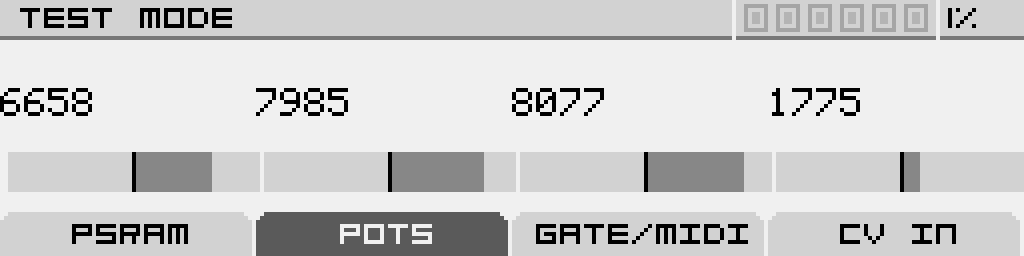
• Allows you to test the functionality of the endless rotary potentiometers. • As you rotate each of the four endless potentiometers, you should see the bar gradually move left or right.
GATE/MIDI
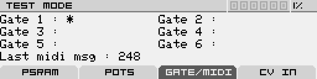
• Verifies the GATE inputs of the main module (1-4) and the expander (5-6).
• A ‘*’ symbol appears next to the input name when a voltage is detected.
• "Last MIDI Message" displays the last received MIDI message (if the MIDI expander is connected).
• If no MIDI message is displayed, this indicates an issue with the MIDI input.
CV
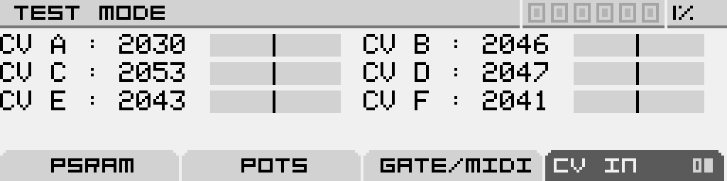
• Displays the real-time value of the CV inputs, ranging from 0 to 4095:
• 0 = -5V
• 2047 ≈ 0V
• 4095 = +5V
The displayed values are raw readings received from the ADC (Analog to Digital Converter) without calibration or smoothing. It is normal to see some fluctuations in the values and for the center value at 0V to not be exactly 2047. It may vary by +/- 20 values. This deviation is corrected during the calibration process.
Calibration
Antigone’s calibration ensures accurate CV input response according to the 1V/oct standard.
If an expander is connected, it is recommended to restart the full calibration process to properly include and adjust the new CV inputs.
Calibration data is stored in Antigone’s Flash memory and remains intact after a firmware update. Therefore, recalibration is not required after updating the firmware.
How to start the calibration?
On Antigone’s main screen "PROJECT", click the burger menu using the encoder, then go to the "SETTINGS" menu and click again to enter.
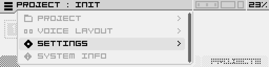
Then select "CALIBRATION".

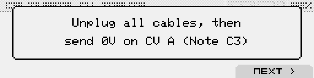
In the calibration screen, you will be asked to unplug all cables connected to the CV inputs (on both the module and the expander).
Next, connect a keyboard (or any voltage source) to the CV A input as shown, and press the C3 key on your keyboard, which usually outputs 0 Volts (depending on your master keyboard’s settings).
Then click the "NEXT" button (button 4) to begin calibration of CV input A. Wait until the progress bar completes.
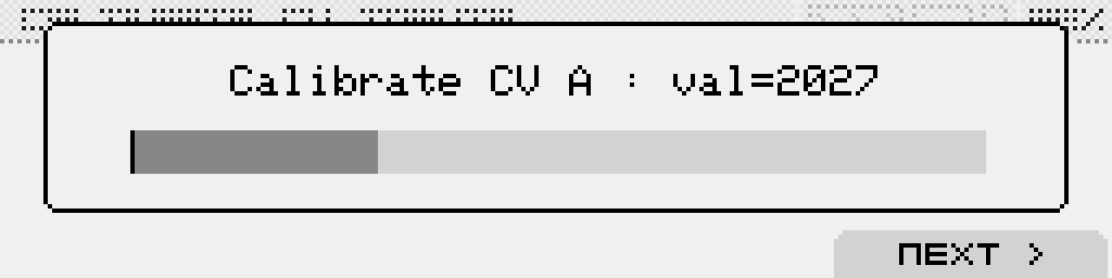
Unplug the cable from CV input A, plug it into CV input B, and repeat the process for each CV input:
- A to F for the main module
- then G to L if the expander is connected.
Once the 0 Volt calibration is done, repeat the entire process for all inputs again using a 3V signal, which corresponds to the C6 note.
After completing the full calibration process, it is recommended to restart the module.